Some simple PyCharm configuration tips & tricks

Way back when, in September 2020, I wrote a blog about how to configure PyCharm for use with ArcGIS Pro (and ArcMap); if you are interested in it then you can read it here. It is the main developer environment I use when I am writing my geoprocessing scripts using ArcPy because it has some great debugging functionality (unlike some applications….) and because it allows you to work with multiple Python environments.

Within the course people often ask a number of PyCharm related questions which usually begin with… “How do I do…?“. So in a bid to collate a few answers to these questions into an accessible location (and mostly to act as an aide for my sieve-like memory) I’ve written this small article which I hope you will find useful…..

I’m going to cover the following things:

  • Stop PyCharm from opening the previous project automatically on start-up.
  • Change the background colour in the script window.
  • Bulk comment and un-comment your code.
  • Indent and un-indent your code.
  • Obtain documentation for a function or a method.

I think that’s plenty to start with so let’s look at the first tip…

Stop PyCharm from opening the last project on start-up

If you have been working in PyCharm and you close the project down then, by default, the same project will open up automatically the next time you start PyCharm – you are not given the opportunity to choose a different project.

How annoying!

It’s quite simple to change this default behaviour in PyCharm.

All you have to do is:

  1. From the File menu > Settings.
  2. Under Appearance & Behaviour, click System Settings.
  3. In the Project group notice the Reopen projects on startup checkbox is ticked.
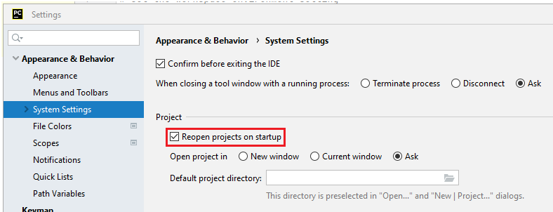
Untick the 'Reopen projects on startup' tick box
  1. Untick the checkbox!
  2. Press the OK button to commit the change you have made on the Settings dialog.

Hopefully the next time you open PyCharm you will then be given the choice as to which project you wish to open, as opposed to open the last project you worked on automatically.

Change the background in the script window

One of the things I always mention to course attendees is how to change the background display of the script window in PyCharm. Annoyingly the background is black which means you can’t see your mouse cursor very easily.

This is because PyCharm’s default colour scheme is called “Darcula”.

It is pretty easy to change, once you know how. Once again, the change can be made within the Appearance & Behavior tab of the Settings dialog box:

  1. From the File menu > Settings > Appearance & Behavior.
  2. Click the Appearance tab.

Notice that the Theme is set to Darcula.

  1. Click the drop down to choose a suitable theme.

You might want to have a look at the Windows 10 Light  or the IntelliJ Light themes.

If you would like a few more themes with the ability to have greater control over the colours within the application then you should look at the Color Scheme section of the Settings dialog; so:

  • File menu > Settings > Editor > Color Scheme > General

The Schemes area provides a number of additional colour schemes with greater control on the parts of the application to which the colour schemes can be applied.

Fill your boots.

Bulk comment and uncomment your code

Many developer environments provide you with the ability to select large swathes of code and through a button either comment or uncomment your code.

PyCharm is ever-so slightly different.

As you are probably aware PyCharm has a very “menu-driven” user interface. There are many menus (11 at the last count) and so finding the correct menu containing the correct item can be a little frustrating.

To comment your code, you can:

  1. Select the code you wish to comment.
  1. Press the <Ctrl> key and then the “/” key to comment your code.
  1. To uncomment your code you perform exactly the same operation.

The equivalent menu item to commentuncomment your code is found through the Code menu > Comment with Line Comment.

Indent and unindent your code

Every time you add error handling to a script, or you work with a compound statement of some description, then you will need to indent your code.

Indenting your code is pretty straight-forward. All you have to do is:

  1. Select your code.
  2. Press the <tab> key.

Your selected code is then indented by one tab width – you probably knew that anyway.

But unindenting your code is a little less obvious. To unindent your code you should carry out the following:

  1. Highlight your code.
  2. Press the <shift> and <tab> keys at the same time.

And your code is then unindented.

These indentation options are also available on the Edit menu.

Display a list of valid parameters for a function or a method

The final thing we will look at is to obtain some floating help for a function or a method.

To display the documentation you should:

  1. Place your mouse cursor between the brackets of the function / method.
  2. If the documentation does not immediately appear then give PyCharm a nudge by pressing <Ctrl> and P at the same time.

So there are my top 5 tips for working with PyCharm. If you have your own comments then please drop them into the comments section below so other people can enjoy your time saving techniques.

Creating ‘T’ Marks in ArcGIS Pro

Lately I’ve been working with a couple of housing associations and one of the things they wanted to cover was how to create ‘T’ marks. The chances are that you may not know what a ‘T’ mark is, especially if you are reading this from outside the UK (I know that many of you are… so ‘Hello World…’) Please do not let that put you off from reading this as I think you might still find this useful, especially of you want to find a particular symbol and it it’s not found in ArcGIS Pro’s installed styles.

So what is a ‘T’ mark?

A ‘T’ mark indicates who is responsible for repair of a wall or fence. They are found predominantly on deed plans. An H mark indicates a shared boundary:

Image available at:
https://www.landregistry-titledeeds.co.uk/frequently-asked-questions/information/title-plan.asp

An Esri UK blog has suggested an alternative workflow for creating these ‘T’ marks but personally I think the described process is a little overly complicated. See what you think… the blog article is found in the following URL:

https://resource.esriuk.com/blog/2019-3-8-how-to-do-polygon-red-lining-and-t-markers-in-arcgis-pro/

If you wish to perform red-lining (i.e. apply a red line internally to a land parcel) then I do recommend you have a look at the Esri UK blog article as that is pretty good.

So how are ‘T’ marks created?

The previous Esri UK blog took you through a process of creating a polyline feature class using 2 polylines, where one polyline joined at the midpoint of the other polyline; you had to create a template..…. as I said a little fiddly. It’s enough to give you Blurred Vision..

Wouldn’t it be easier to….?

1: Create a point feature class

2: Set appropriate symbology using a glyph (icon) in a font.

3: Rotate the symbol to capture its relationship to the underlying map base.

Let’s go through the steps to create a point-based ‘T’ mark which automatically captures the rotation angle.

Step 1: Create a Point feature class

The first thing you should do is create a point feature class in a suitable geodatabase. This is pretty straight forward to do so I’m not going into detail about how to do that.

A couple of things to note though:

1: Make sure the geometry type is set to point

2: Create a new attribute field called Rotation whose data type is Short Integer.

The Rotation attribute field will store the angle of rotation of the ‘T’ marks and might be useful for other non-Esri systems should you ever wish to export the data out.

When the new T Marks feature class is added to the map it will be symbolised as a standard non-descript point symbol.

You will need to symbolise the feature with the appropriate ‘T’ mark symbology.

2: Symbolise the ‘T’ Marks

You will now look for the ‘T’ symbol which will be used to symbolise your ‘T’ marks. You will take advantage of the fonts that are installed on your operating system and use a glyph found in one of the fonts.

1: Choose the Single Symbol renderer to display the Symbology pane.

2: Click the actual symbol to display the Gallery and then Properties tab > Layers button to display the layering characteristics of the point symbol.

The renderer type is currently set to Shape marker. You are going to change its appearance by choosing a particular glyph from an existing font.

3: Under Appearance choose Font.

4: In the Choose a character dialog box make sure the Font is Arial and the Font style is Regular.

5: For Subset choose Combining Diacritical Marks and browse to the end of the glyph list and choose the inverted T glyph. It has a Unicode of 880.

6: And press the OK button.

The glyph is added to the Format Point Symbology pane. You will need to change its properties to display the ‘T’ marker symbol correctly.

7: Set the following properties:

  • Size: 29 pts
  • Shape fill symbol: red.
  • Outline color to red.
  • Outline width to 0.

You will now rotate the ‘T’ Marker symbol so it is standing upright and not on its side.

8: Locate the Rotation entry and choose 270 degrees for the Angle.

Your efforts will produce the following symbol:

Currently, if you add a ‘T’ mark to the map it will be positioned centrally due to the positioning of the icon’s geometric centre. Ideally you want the bottom of the ‘T’ mark to be displayed on the boundary which means moving the geometric centre to the end of the ‘T’ mark.

9: Click the Show geometry button to display the geometric centre of the icon.

You should now offset the symbol.

10: Click the Offset Distance entry and enter a value of 9 pt for Offset Y and an optional Offset X of -1pt.

The base of the ‘T’ marker now rests on the X which indicates the position at which the ‘T’ marker will be positioned on the map. This will rest against the boundary feature.

11: Press the Apply button on the dialog.

That is all you need to establish the base symbology for the ‘T’ marker. The symbology will be applied to the legend for the ‘T’ mark layer in the Contents pane.

3: Capture the rotation angle of the T mark

Do you remember creating the Rotation field? You can automatically populate that field with the rotation angle of the ‘T’ mark in relation to the boundary when a ‘T’ mark is added to the map.

1: Press the back arrow at the top of the Symbology – T Marks pane to take you back to the primary symbology pane.

2: Click the Vary symbology by attribute button, expand the Rotation category and choose the Rotation field.

3: Set the Rotation Style to Geographic.

And that is it!

As you can see you have performed a fair amount of configuration so it might make sense to export these settings out to a Layer (.lyrx) File.

You are now ready to capture your ‘T’ markers.

Capture a ‘T’ mark

1: Set the map scale to 1:500.

2: Click the Edit tab and confirm that the T Markers editing template has been created by clicking the Create Features button.

3: Choose the T Marks template and choose the Point construction tool.

As you move the cursor over the map base notice that the base of the marker point acts as the anchor point for the new feature. You can use this anchor point to snap to the underlying feature geometry.

4: Add a new ‘T’ mark to the map.

The newly added ‘T’ mark is automatically selected and is ready to be rotated.

Let’s rotate the feature.
5: With the ‘T’ mark selected, click the Modify Features button to display the Modify Features pane.

6: Click the Rotate tool.

The selected ‘T’ mark is now ready to be rotated.

7: Rotate the ‘T’ mark so it is perpendicular to the land parcel outline.

8: Press the Finish button to complete the edits of your sketch.

Here’s a nice surprise…. If you open the Attributes pane the you will see that the Rotation field is automatically filled in!

Having the ‘T’ mark as a point feature class with an associated rotation angle is handy should you ever need to export the dataset to A N Other GIS system and you wish to replicate the rotation.

And there you have it! The workflow has taken you through, step – by – step, how to create a point-based ‘T’ mark with rotation.

In doing to you have learned how to access a font and symbolise a glyph by specifying a few of its properties. Hopefully this has given you a glimpse into some useful symbology techniques you can apply through ArcGIS Pro.